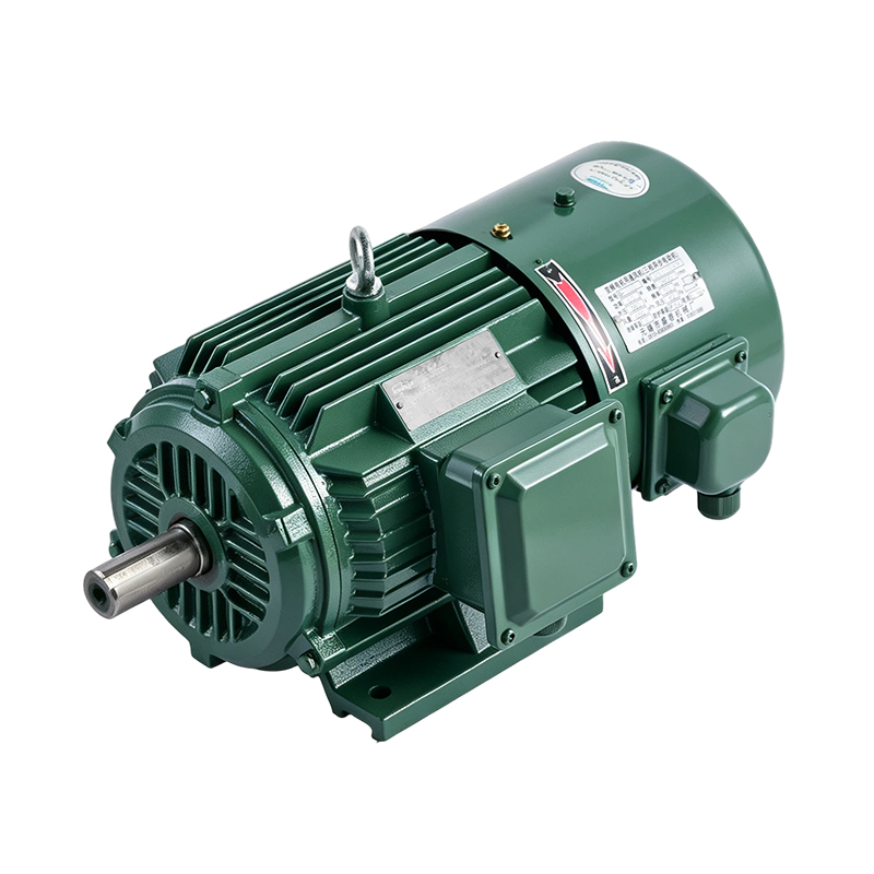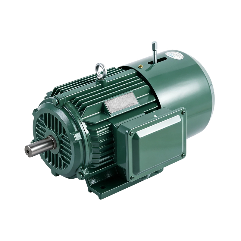

 English
 Español
 عربى
Content
- 1 Quick Answer: How 2 Pole, 4 Pole and 6 Pole Motors Differ
- 2 How Pole Count Sets Speed in a 3 Phase AC Induction Motor
- 3 2 Pole Motors: High Speed for Fans, Pumps and Compressors
- 4 4 Pole Motors: The General Purpose Workhorse
- 5 6 Pole Motors: Lower Speed, Higher Torque and Quieter Running
- 6 Torque and Frame Size: A Worked 11 kW Example
- 7 2 Pole vs 4 Pole vs 6 Pole: Side by Side Comparison
- 8 Speed and Performance Charts at a Glance
- 9 Inside a Three Phase AC Motor: Where Poles Come From
- 10 Matching Pole Count to the Driven Equipment
- 11 IE3 vs IE2 Three Phase Motor: What Changes Beyond the Nameplate
- 12 How to Choose the Right Pole Count Step by Step
- 13 Variable Frequency Drives and Multi Speed Motors
- 14 Common Selection Mistakes to Avoid
- 15 Zhejiang Kuayue Motor: An IE3 Motor Manufacturer for Industrial Users
- 16 Three Phase Motors by Pole Count From Kuayue Motor
- 17 Custom Three Phase Induction Motors for OEM Equipment
- 18 Frequently Asked Questions About 2, 4 and 6 Pole Motors
- 18.1 Q1. What is the difference between a 2 pole and a 4 pole induction motor?
- 18.2 Q2. Which is better for a pump, a 2 pole or 4 pole motor?
- 18.3 Q3. What speed does a 6 pole motor run at on 50 Hz?
- 18.4 Q4. Does a higher pole count mean more torque?
- 18.5 Q5. Can a 4 pole motor run on a 60 Hz supply?
- 18.6 Q6. What is the difference between IE2 and IE3 three phase motors?
- 18.7 Q7. What does IP55 mean on a three phase motor?
- 18.8 Q8. How do I choose a motor for an air compressor?
- 18.9 Q9. Can I change the speed of a motor without changing poles?
- 18.10 Q10. Does Kuayue Motor offer custom three phase motors?
Quick Answer: How 2 Pole, 4 Pole and 6 Pole Motors Differ
The number of poles sets how fast the rotating magnetic field turns, and that fixes the speed class of a Three Phase Induction Motor. On a 50 Hz supply a 2 pole motor has a synchronous speed of 3,000 rpm, a 4 pole motor 1,500 rpm and a 6 pole motor 1,000 rpm. On a 60 Hz supply the same three designs run at 3,600, 1,800 and 1,200 rpm.
2 pole: 3,000 rpm4 pole: 1,500 rpm6 pole: 1,000 rpm50 Hz synchronous speed
At the same kilowatt rating, a slower motor delivers more shaft torque, so a 6 pole machine produces roughly three times the torque of a 2 pole machine of equal power. That extra torque comes with a larger frame, a different noise profile and a different match to the driven equipment. A 3 phase AC induction motor therefore needs to be chosen by speed first, then by torque, load type and duty.
Fast Selection Guide
- 2 pole: high speed loads such as centrifugal fans, high head pumps and some compressors.
- 4 pole: the most common general purpose choice for conveyors, mixers, pumps and machine tools.
- 6 pole: lower speed, higher torque and quieter running for crushers, large fans, hoists and direct drive equipment.
The values in this article come from the standard synchronous speed relation and from catalog information published by Zhejiang Kuayue Motor Co., Ltd. Where a figure is a worked example rather than a measured result, the text says so.
How Pole Count Sets Speed in a 3 Phase AC Induction Motor
A Three Phase AC Motor creates a rotating magnetic field when balanced three phase current flows through the stator windings. The field turns at synchronous speed, which depends only on the supply frequency and the number of poles wound into the stator. The relation is one of the first formulas taught in electrical machines courses.
Ns = 120 x f / P
Ns is synchronous speed in rpm, f is supply frequency in hertz and P is the number of poles. A 4 pole motor on 50 Hz gives 120 x 50 / 4 = 1,500 rpm. Doubling the pole count halves the speed, which is why speed classes follow the pattern 3,000, 1,500, 1,000 and 750 rpm at 50 Hz.
Why the Rotor Never Reaches Synchronous Speed
The rotor is turned by current that the rotating field induces in its conductors. That induction only happens when the rotor moves slightly slower than the field. The speed gap is called slip. A 4 pole motor running at 1,450 rpm on a 50 Hz supply has a slip of about 3.3 percent, calculated as (1,500 minus 1,450) divided by 1,500. This is the reason the machine is also called an asynchronous motor.
| Pole Count | 50 Hz Synchronous | 60 Hz Synchronous | Typical Nameplate at 50 Hz |
|---|---|---|---|
| 2 pole | 3,000 rpm | 3,600 rpm | 2,900 to 2,970 rpm |
| 4 pole | 1,500 rpm | 1,800 rpm | 1,430 to 1,480 rpm |
| 6 pole | 1,000 rpm | 1,200 rpm | 950 to 990 rpm |
| 8 pole | 750 rpm | 900 rpm | 710 to 740 rpm |
2 Pole Motors: High Speed for Fans, Pumps and Compressors
A 2 pole motor is the fastest standard speed class, with a synchronous speed of 3,000 rpm at 50 Hz and 3,600 rpm at 60 Hz. Its winding has the fewest coil groups, which keeps the stator compact and the rotor diameter modest for a given power. For loads that want high shaft speed, the motor can often be coupled directly with no gearbox or belt.
Where 2 Pole Motors Fit
Centrifugal pumps that need high head, high speed blowers, some screw compressor designs and machine tool spindles are common matches. For centrifugal loads the affinity laws apply: flow changes in proportion to speed, head with the square of speed and power with the cube of speed. A fast motor lets a small impeller reach the required head, which keeps the pump set compact.
For energy sensitive sites, an IE3 Motor for Industrial Pumps in the 2 pole class can reduce losses on duty cycles with long running hours, provided the pump operating point sits close to the motor rating.
4 Pole Motors: The General Purpose Workhorse
The 4 pole motor, at 1,500 rpm on 50 Hz and 1,800 rpm on 60 Hz, is the most widely stocked configuration of the Three Phase Induction Motor. Many catalog frame tables, mounting dimensions and efficiency tables are written around it, and the speed suits a very large share of everyday mechanical equipment.
Balanced Speed and Torque
Compared with a 2 pole machine of equal power, a 4 pole machine has about twice the rated torque and half the shaft speed. That balance works with belt drives, gearboxes and direct coupling alike. Noise and vibration are lower than in 2 pole designs, and bearing life is usually less sensitive to small alignment errors.
Typical Uses
- Belt and screw conveyors, mixers and agitators.
- General water pumps and circulation pumps.
- Piston air compressors driven through a belt.
- Machine tools, packaging lines and textile equipment.
An IE3 Motor for Air Compressors in the 4 pole class is a frequent specification, because compressors often run long hours and the speed fits common belt ratios. Compressor makers state the required shaft speed and starting torque, and those two figures usually decide between 2 and 4 pole.
6 Pole Motors: Lower Speed, Higher Torque and Quieter Running
A 6 pole motor turns at 1,000 rpm on 50 Hz and 1,200 rpm on 60 Hz. At equal power it delivers about three times the rated torque of a 2 pole machine. The frame is larger and heavier, but the lower speed reduces fan noise, bearing speed and centrifugal stress on the rotor.
When Slower Is the Better Fit
Equipment that would otherwise need a gearbox to bring 1,500 rpm down to a working speed can sometimes use a 6 pole motor directly. Large fans, crushers, ball mills, heavy conveyors and hoists are typical examples. Removing a reduction stage can simplify the drive train, although the larger motor frame must fit the available space.
Notes on 8 Pole and Slower Motors
An 8 pole motor runs at 750 rpm on 50 Hz and delivers about four times the torque of a 2 pole machine at equal power. These motors suit low speed direct drive loads such as slow fans and some pumps. Frame size grows quickly, so most buyers compare an 8 pole motor against a 6 pole motor with a gearbox before deciding.
- Direct drive of slow, heavy loads.
- Lower noise in occupied buildings and ventilation plant.
- Lower bearing speed, which suits long continuous duty.
Torque and Frame Size: A Worked 11 kW Example
Shaft power equals torque multiplied by angular speed. In practical units, torque in newton metres is about 9,550 x power in kilowatts / speed in rpm. For a fixed power, torque rises as speed falls. The table below uses an 11 kW rating and assumed full load speeds near typical nameplate values. These are calculated illustration figures, not catalog data for a specific motor.
| Pole Count | Assumed Speed | Torque at 11 kW | Versus 2 Pole |
|---|---|---|---|
| 2 pole | 2,930 rpm | 35.9 Nm | 1.0 x |
| 4 pole | 1,460 rpm | 72.0 Nm | 2.0 x |
| 6 pole | 970 rpm | 108.3 Nm | 3.0 x |
| 8 pole | 730 rpm | 143.9 Nm | 4.0 x |
Frame size follows torque more closely than it follows power, because rotor and stator dimensions are sized to carry magnetic flux and thermal load tied to torque. That is why a 6 pole motor of the same kilowatt rating is typically longer or wider than its 4 pole sibling, and why mounting space should be checked early in a design.
2 Pole vs 4 Pole vs 6 Pole: Side by Side Comparison
The table gathers the main differences in one place. Use it as a first screening step, then confirm details against the nameplate and the driven equipment data sheet.
| Feature | 2 Pole | 4 Pole | 6 Pole |
|---|---|---|---|
| Synchronous speed | 3,000 rpm | 1,500 rpm | 1,000 rpm |
| Rated torque | Lowest | Medium | Higher |
| Frame size | Most compact | Moderate | Larger |
| Noise tendency | Higher | Moderate | Lower |
| Typical drive | Direct to fan or pump | Belt, gearbox or direct | Direct to slow load |
| Common loads | Fans, high head pumps | Conveyors, mixers, pumps | Crushers, hoists, slow fans |
Speed and Performance Charts at a Glance
The three charts below translate the formulas and comparisons above into pictures. The first two use calculated synchronous speeds, and the third is an illustrative engineering scale rather than test data.
Synchronous Speed on a 60 Hz Supply
Markets that use 60 Hz see speeds 20 percent higher than the 50 Hz values for the same pole count. A motor built for 50 Hz should only be run on 60 Hz after the nameplate voltage and frequency data have been checked.
Speed Against Pole Count at 50 Hz and 60 Hz
The line chart shows how quickly speed falls as poles are added. The drop from 2 to 4 poles is large in absolute terms, while the step from 6 to 8 poles is small, which is one reason 2, 4 and 6 pole motors cover most industrial duty.
Relative Suitability Radar Chart
The radar chart compares the three speed classes on five qualities using a 1 to 5 relative scale. It is an engineering judgment aid built from the general tendencies described earlier, not a measured test result, and individual motor designs will differ.
Inside a Three Phase AC Motor: Where Poles Come From
The pole count is not an add on part. It is set by how the stator winding is arranged in the slots of the stator core. A 2 pole winding creates one north and one south pole around the bore, a 4 pole winding creates two of each, and a 6 pole winding creates three of each. The outer frame can look almost identical across the three classes, which is why the nameplate is the only reliable way to read the speed class.
Main Parts and What They Do
- Stator core and winding: carry the three phase current and create the rotating field. The winding layout sets the pole count.
- Squirrel cage rotor: bars joined by end rings, which carry induced current and produce torque with no brushes or slip rings.
- Frame and fins: cast iron or aluminum alloy housing that carries the stator and sheds heat to the cooling air.
- End covers and bearings: hold the shaft in position and carry radial and axial load.
- Terminal box: where the supply cable connects to the winding, in star or delta arrangement according to the nameplate.
Matching Pole Count to the Driven Equipment
Starting from the load rather than from the motor catalog avoids most selection errors. The driven equipment sets the required shaft speed, torque curve and duty cycle. The pole count that meets those three items with the least mechanical complexity is usually the right one.
IE3 Motor for Industrial Pumps
Pumps often run for thousands of hours each year, so motor losses translate into a steady electricity load. Pairing a pump with an IE3 motor reduces those losses, and matching the pole count to the pump design keeps the operating point close to the best efficiency range of the pump. The affinity laws also show why speed matters: lowering a centrifugal pump to 80 percent speed cuts shaft power to about 51 percent, since 0.8 cubed is 0.512.
IE3 Motor for Air Compressors
Compressor duty combines high starting torque with long running hours. An IE3 motor lowers heat generation inside the winding, which supports stable operation under continuous load. Confirm the starting torque of the motor against the compressor unloaded and loaded start requirements before ordering.
IE3 vs IE2 Three Phase Motor: What Changes Beyond the Nameplate
IE stands for International Efficiency, a classification of motor efficiency levels described in the IEC 60034-30-1 standard. The 2025 edition extends the framework to include IE5 and covers single speed AC motors from 0.12 kW to 1,000 kW in 2, 4, 6 and 8 pole configurations. Each step up the scale lowers the electrical losses of a motor at the same output.
The practical effect shows up in running hours. Consider a 75 kW output at full load. At 94 percent efficiency the motor draws about 79.8 kW from the supply, and at 95 percent it draws about 78.9 kW. The difference is roughly 0.84 kW, which over 6,000 operating hours is about 5,000 kWh per year. This is a calculation example, and real savings depend on load profile and motor design.
Reading the Efficiency Class Correctly
- Check the IE class printed on the nameplate rather than relying on marketing terms such as premium or high efficiency.
- Compare efficiency at the same pole count and power rating, because efficiency values differ between 2, 4 and 6 pole motors.
- Ask for part load efficiency at 75 percent and 50 percent load when the motor will not run at full load.
- Note that efficient motors often run at slightly higher speed than older designs, which can raise power draw on fan and pump loads.
How to Choose the Right Pole Count Step by Step
A short, ordered routine keeps the decision clear when several motors look similar on paper.
- Write down the required shaft speed and the power at that speed from the driven equipment data sheet.
- Choose the pole count whose rated speed sits closest to that figure on the available supply frequency.
- Check the torque demand at start and at peak load against the motor starting and breakdown torque.
- Confirm voltage, frequency, duty class, ambient temperature, altitude and mounting arrangement.
- Check the available space, since lower speed motors have larger frames at the same power.
- Select the efficiency class, with IE3 as a common baseline for long running hours.
- Confirm enclosure protection, insulation class and any special requirement such as a brake or explosion protection.
- Review the full nameplate on delivery against the order specification.
Variable Frequency Drives and Multi Speed Motors
A frequency inverter changes motor speed by changing the supply frequency, so the pole count stays fixed while the speed moves above or below the base value. A 4 pole motor on a 25 Hz inverter output has a synchronous speed of 750 rpm. This is useful for pumps and fans, where speed control saves energy under varying demand.
Points to Check With Inverter Duty
- Cooling drops at low speed on motors with a shaft mounted fan, so continuous low speed torque may need a derating check.
- Insulation and bearings see higher stress from inverter switching, so inverter duty designs are available for this purpose.
- Running well above base frequency reduces available torque, because the motor enters the field weakening range.
Multi Speed Pole Changing Motors
Where only two or three fixed speeds are needed, a multi speed motor changes the winding connection to switch between pole counts. A two speed design can offer 1,500 and 3,000 rpm, or 1,000 and 1,500 rpm. These motors avoid the cost and complexity of an inverter for simple duty such as a two stage fan or a machine with a slow and a fast mode.
Common Selection Mistakes to Avoid
Most field problems with speed class choice trace back to a short list of oversights.
- Reading kilowatts only: two motors with the same kW can differ in torque by a factor of two or more when the pole count differs.
- Replacing a motor by frame size alone: a replacement with the same mounting but a different pole count changes the speed of the driven machine.
- Ignoring slip differences: a more efficient motor may run a few rpm faster, which can raise pump and fan load.
- Running 50 Hz motors on 60 Hz without a check: speed rises by 20 percent and voltage matching becomes important.
- Oversizing by a wide margin: a lightly loaded motor runs at lower efficiency and power factor than one sized close to the load.
- Skipping the start torque check: loaded starts on compressors and conveyors may need more torque than a small frame provides.
Zhejiang Kuayue Motor: An IE3 Motor Manufacturer for Industrial Users
Zhejiang Kuayue Motor Co., Ltd. is an export oriented manufacturer that combines research and development, production, sales and export. The company is located in Luqiao District, Taizhou City, Zhejiang Province, and has accumulated 34 years of experience in the motor industry. As an IE3 Motor Manufacturer and Three Phase Induction Motor supplier, it provides three phase asynchronous motors and industrial pump solutions to customers worldwide.
The three phase asynchronous motor range covers 2, 4, 6 and 8 pole configurations, from high speed light load duty to low speed heavy load duty. Housings are made from high strength cast iron or lightweight aluminum alloy, with Class F insulation and IP55 protection. Motors serve mining, chemical processing, pump and HVAC, textile, lifting, machine tool and port construction machinery, and are exported to Europe, America, Southeast Asia and the Middle East.
Special configurations extend beyond standard duty, including multi speed motors, electromagnetic brake motors, variable frequency motors and explosion proof motors for settings such as coal mines and petrochemical plants.
Three Phase Motors by Pole Count From Kuayue Motor
The cards below show motors from the Three Phase Asynchronous Motors catalog that match the 2, 4 and 6 pole classes discussed above. Each links to its product page for specifications.
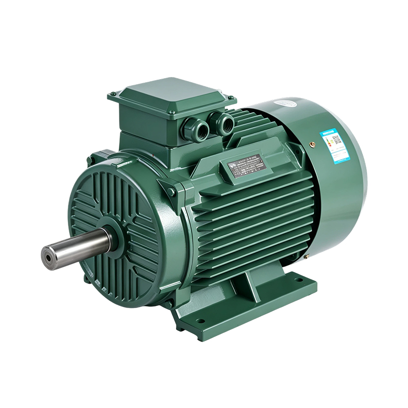 2 PoleYE4/IE4 High-Speed Energy-Saving Induction Motor (2-pole)View Details
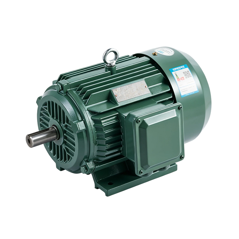 4 PoleYE3/IE3 General-Purpose High-Efficiency Induction Motor (4-pole)View Details 6 PoleYE3/IE3 Heavy-Duty High-Efficiency Induction Motor (6-pole)View Details
Custom Three Phase Induction Motors for OEM Equipment
Equipment builders often need a motor that differs from a catalog item: a special shaft, a non standard flange, a different voltage or a particular mounting position. As a Custom Three Phase Induction Motor Manufacturer, Kuayue Motor offers ODM and OEM customization services built on its standard motor platforms. The same approach applies as a Custom IE3 Motor Manufacturer, where the efficiency class, pole count and frame are agreed with the customer before production.
Information That Speeds Up a Custom Request
- Rated power, pole count or required output speed.
- Supply voltage and frequency, including any 50 Hz and 60 Hz dual use.
- Mounting type, shaft dimensions and any flange drawing.
- Duty type, ambient conditions and enclosure protection needs.
- Options such as a brake, inverter duty winding or explosion protection.
As an Industrial Motor Manufacturer for OEM Equipment and an Industrial Electric Motor Wholesale Supplier, the company supports both single machine builders and distributors who stock several frame sizes. Specification details are confirmed through the contact form on the official website.
Special Duty Motors in the Catalog
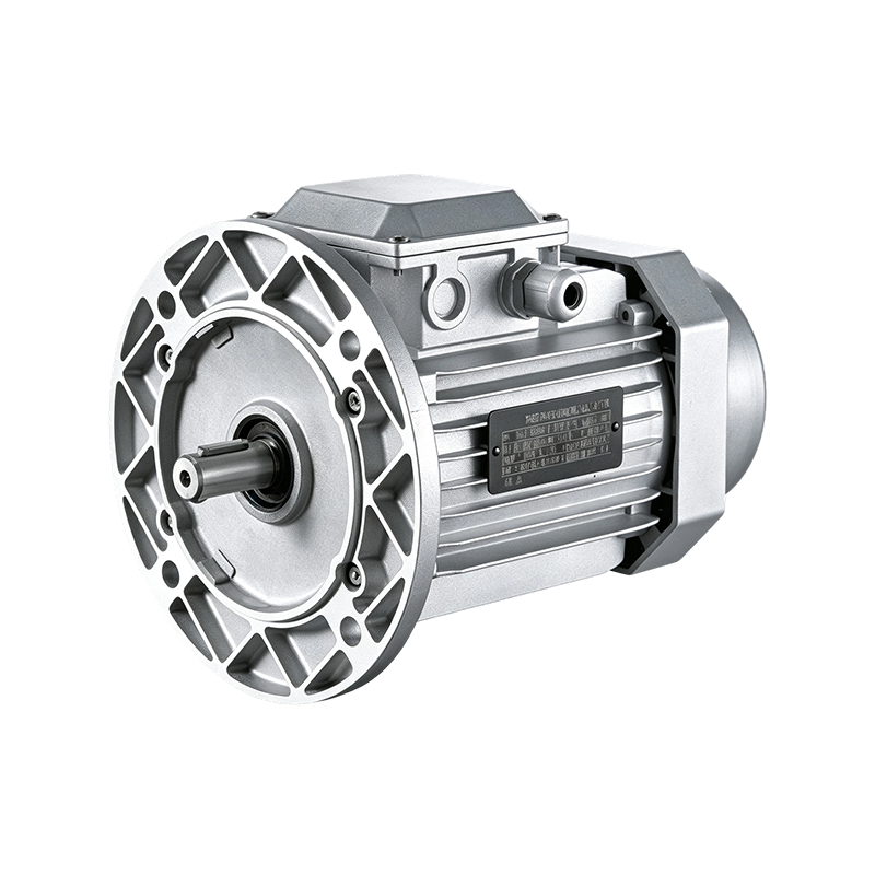 Aluminum ShellYE3/IE3 High-Speed Aluminum Shell Induction Motor (2-pole)View Details
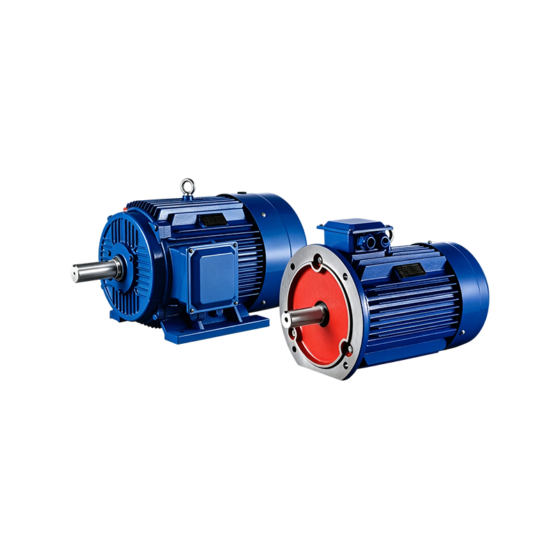 Two SpeedYD2 Standard Two-Speed Induction Motor (1500/3000 RPM)View Details
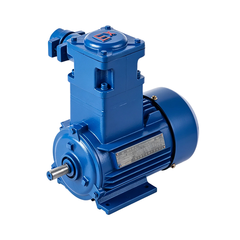 Explosion ProofYBX3 Standard Explosion-Proof Induction Motor (4-pole)View Details