Quickly find the product you need.

A 15 kW pump motor can pass a bench test and still trip a thermal relay after 20 minutes at 80% load. The cause is often not the winding but a mismatch between load torque, cooling, and the selected motor variant. The three-phase asynchronous induction motor is a mature, self-starting machine, yet it is not a drop-in commodity. The practical conclusion: select by torque profile, duty cycle, efficiency class, enclosure, and control method before comparing price. Get those five points right and the motor usually runs quietly for years. Miss one and the coupling, contactor, or gearbox may become the next weak point.
This guide explains how the motor works, where slip and efficiency affect real operating cost, and which checks reduce procurement and maintenance risk.
Content
A three-phase stator winding creates a rotating magnetic field. The field speed is synchronous speed: ns = 120f / p, where f is supply frequency and p is pole count. At 50 Hz, a 4-pole motor has a synchronous speed of 1,500 rpm. The rotor does not run at that speed. Relative motion between the rotating field and the rotor bars induces current in the rotor, and that current produces torque. The difference between synchronous speed and rotor speed is slip, usually a few percent at full load.
Slip is not a defect. It is the mechanism that lets the machine deliver torque. Too little slip at a given load may indicate an oversized motor running lightly loaded; too much slip can show overload, low voltage, or a rotor problem. A clamp meter, tachometer, and nameplate check tell more than a guess.
The chart uses a typical 4-pole, 50 Hz example. Actual slip depends on rotor resistance, load, and design. A motor rated at 1,450 rpm at full load is not the same as one rated at 1,480 rpm, even if both are 4-pole machines.
IEC 60034-30-1 sets efficiency classes for line-fed induction motors. IE3 is the common high-efficiency baseline; IE4 is the super-premium class. The difference is not just a label. Higher efficiency usually means more active material, tighter manufacturing control, and a different price point. For a motor running 4,000 hours a year, a two-point efficiency gain can outweigh a small purchase premium, but the payback depends on load profile, energy price, and actual hours.
Use the nameplate and test certificate, not catalogue headlines. Check efficiency at full load and at part load if the duty is variable. A motor that is highly efficient at 100% load but runs at 30% load most of the year may not deliver the expected saving. For a more detailed class comparison, see this IE3 vs IE4 motor comparison.
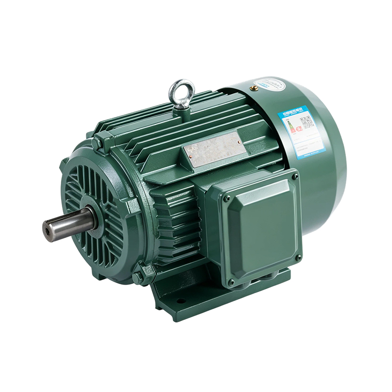
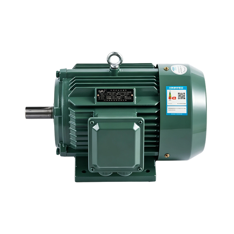 YE3/IE3 General-Purpose High-Efficiency 4-Pole Induction MotorA 0.55–315 kW, 1500 RPM series to check against nameplate efficiency, frame, mounting, and driven-machine duty before selecting.View Product →
For general-purpose 4-pole duties, the YE3/IE3 high-efficiency series is one starting point, but confirm frame, mounting, and efficiency data against the driven machine.
Start with torque, not kW. A conveyor, crusher, or positive-displacement pump may demand high starting torque and a design that can accelerate the load. A fan or centrifugal pump normally has a lower starting demand. The motor must have enough breakdown torque to ride through voltage dips and enough starting torque to accelerate the driven machine without excessive heating.
The table below turns common purchase risks into checks.
| Requirement | What to check | Risk if missed |
|---|---|---|
| Load torque and start profile | Compare starting, pull-up, and breakdown torque with the driven machine curve | Stall, coupling wear, nuisance trips |
| Duty cycle | Continuous, intermittent, reversing, and starts per hour | Overheating and shortened insulation life |
| Environment | Dust, water, humidity, ambient temperature, hazardous gas | Corrosion, insulation failure, unsafe operation |
| Efficiency and power factor | IE3 or IE4 class, part-load efficiency, utility rebate | Higher running cost and oversized current |
| Mounting and control | Foot or flange, shaft fit, DOL, soft starter, VFD, brake | Vibration, bearing failure, harmonics, insulation stress |
For mining and heavy conveying, the duty cycle often includes dust, shock loading, and frequent starts; the surrounding equipment deserves the same attention as the motor. A mining machinery solution overview can help frame those checks.
When the load must hold position or stop quickly, a brake motor changes the selection. Check brake torque, release time, and starts per hour; a general-purpose positioning brake motor is a different purchase from a holding brake.
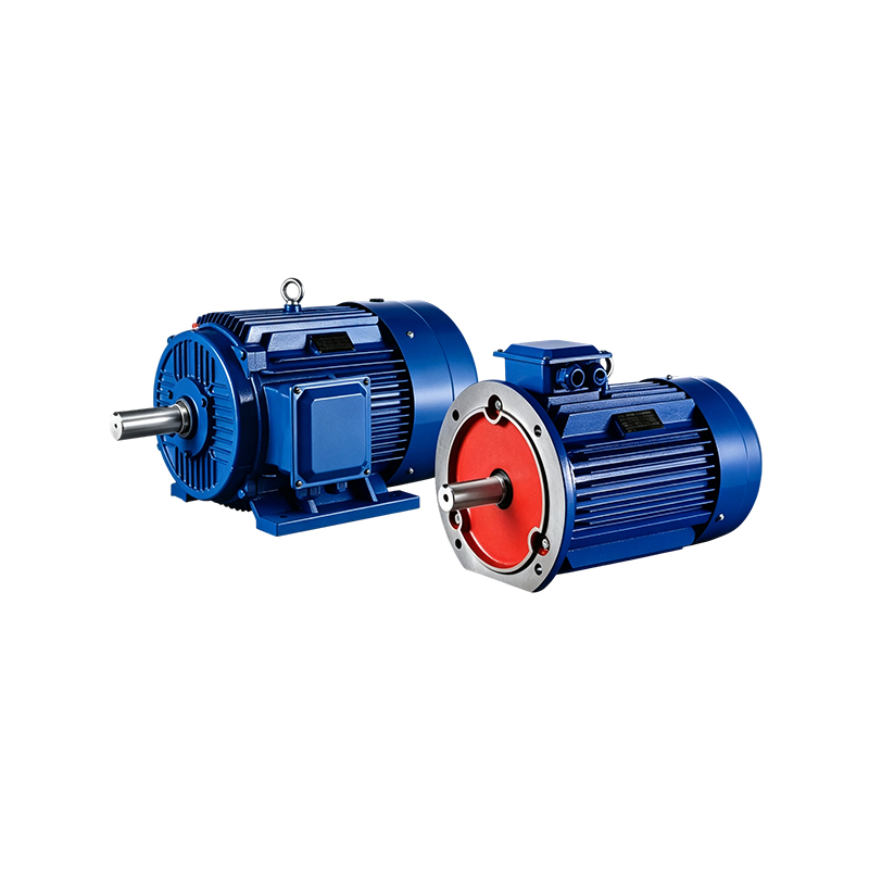
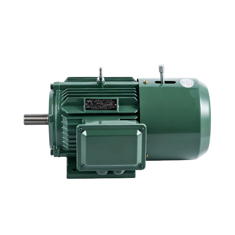 YEJ2 General-Purpose Positioning Brake Motor, 4-PoleFor stopping or holding position, this 0.55–45 kW brake motor needs brake torque, release time, and starts-per-hour checked against the load.View Product →
The basic squirrel-cage motor becomes a family once the application adds stopping, hazardous location, or speed control. An electromagnetic brake motor integrates a brake at the non-drive end. It is used for hoists, packaging machines, and positioning axes where coasting is unacceptable. Check brake torque against load torque, release time against cycle time, and brake wear against starts per hour. A brake that is strong enough but slow to release can overheat.
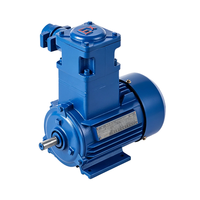
Explosion-proof motors are not ordinary motors in a heavier box. The enclosure, flame paths, terminal chamber, and certification must match the hazardous area classification and gas group. A common mistake is selecting by kW and frame while ignoring the Ex marking, temperature class, and local approval requirements. In dust or gas zones, the motor nameplate and certificate are part of the safety case.
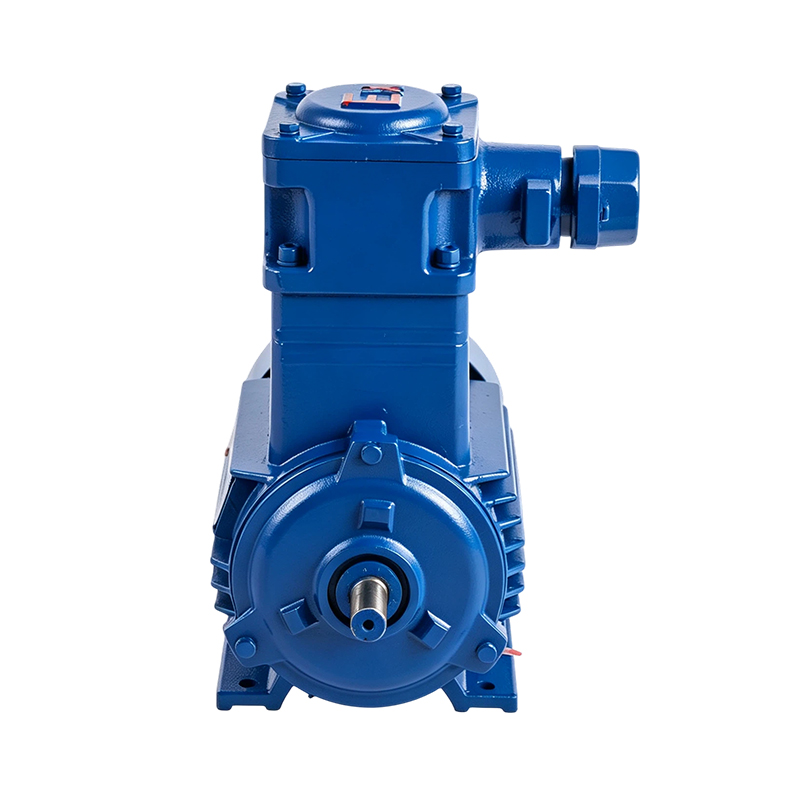 YBX3 Standard Explosion-Proof 4-Pole Induction MotorA 0.12–315 kW Exd IIB T4/CT4 motor for hazardous gas or dust areas; verify Ex marking, temperature class, and local approval against the zone.View Product →
Variable-frequency duty adds another layer. Standard motors can run on a VFD within a defined speed range, but insulation, bearing current, cooling at low speed, and cable length need review. Inverter-duty motors and separate cooling fans are common where constant torque is required below base speed.
Most premature failures are not mysterious. They come from misalignment, overload, moisture, loose terminals, or blocked cooling. The diagram shows the main check points on a totally enclosed fan-cooled induction motor.
Before start-up, confirm shaft alignment and belt tension, check that the fan cover and cooling fins are clear, and verify terminal torque against the manufacturer's data. Measure insulation resistance if the motor has been stored in damp conditions. After start-up, record current on all phases, vibration, and bearing temperature at steady load. A phase imbalance of a few percent can produce a noticeable current imbalance and extra heating.
It drives pumps, fans, conveyors, compressors, machine tools, and other industrial loads where a robust, self-starting motor is needed.
IE4 has a higher minimum efficiency class than IE3 under IEC 60034-30-1, but the saving depends on load profile, running hours, and purchase price.
Use I = P / (√3 × V × power factor × efficiency), with P in watts. Use nameplate values when available; the result is an estimate for cable and protection checks.
Common causes include overload, low voltage, phase imbalance, blocked cooling, high ambient temperature, and too many starts per hour.
Yes, within the motor's approved speed range. Check insulation, cooling at low speed, cable length, and bearing current; inverter-duty designs are preferred for constant torque below base speed.
Match the Ex marking, gas or dust group, temperature class, enclosure, frame, mounting, and certificate. Do not substitute a standard motor in a hazardous area.



 English
 Español
 عربى