Quickly find the product you need.

Content
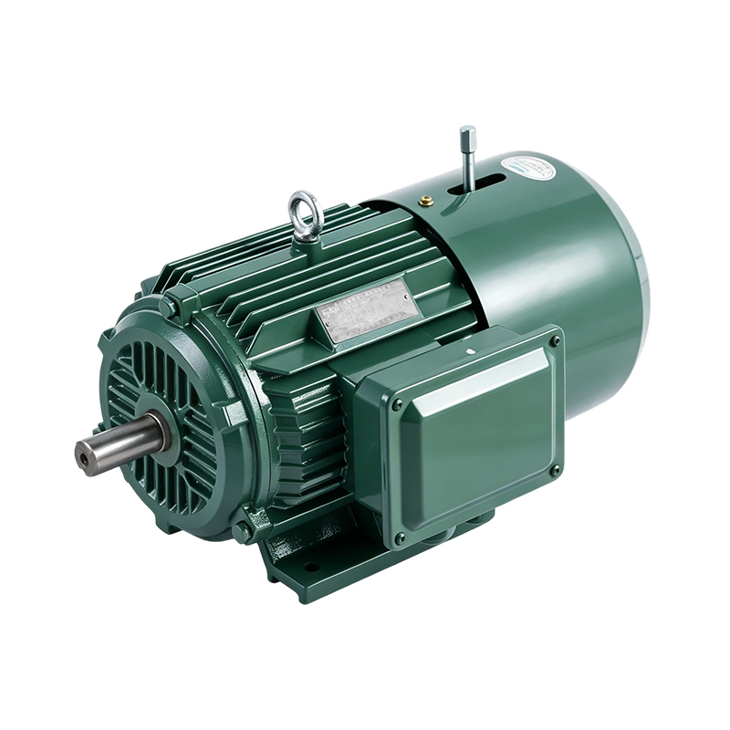
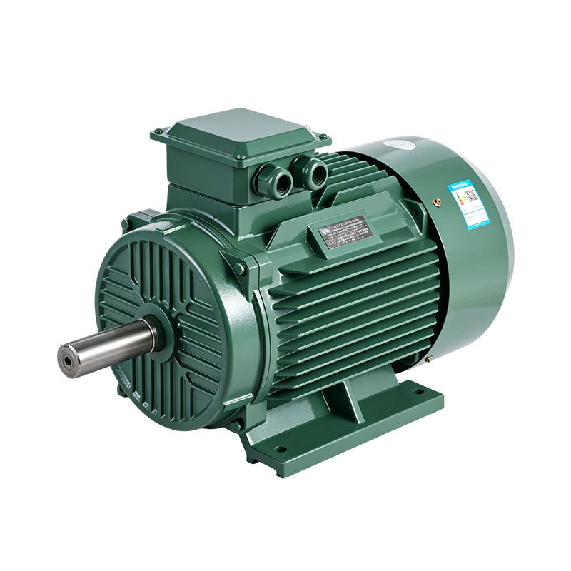
A three-phase asynchronous motor is an AC machine that turns three-phase electrical power into rotating mechanical power through electromagnetic induction rather than through a direct electrical connection to the rotor. A rotating magnetic field is produced in the stator windings, and this field induces current in the rotor bars, which in turn generates torque. The rotor speed always trails the speed of the rotating field by a small margin called slip, which is exactly why this machine is also known as a three phase induction motor.
Because it needs no brushes, no external rotor excitation, and no capacitor to start, the three-phase asynchronous motor has become the standard three phase electric motor for factories, workshops and utility plants. Typical product ranges span from small fractional units around 0.09 kW up to large frame sizes around 375 kW, with 2, 4, 6 and 8-pole winding options covering everything from high-speed light-load fans to low-speed heavy-load conveyors. Housings are commonly built from high-strength cast iron or lightweight aluminum alloy, paired with Class F insulation and an IP55 protection rating for dust and light water exposure.
In short, when someone searches for a 3 phase induction motor or a three phase AC motor, they are almost always describing this same family of machines. The remaining sections below walk through how it works, what it is made of, how to read its data plate, and how to size one correctly for a given job.
Three separate winding groups are placed 120 electrical degrees apart inside the stator. When three-phase current flows through them in sequence, the combined magnetic field does not stay fixed in one spot — it rotates around the inside of the stator bore at a speed known as synchronous speed. Synchronous speed depends only on the supply frequency and the number of poles wound into the stator, following the relationship Ns = 120 x f / P, where f is frequency in hertz and P is the pole count.
The rotor bars sit inside this rotating field but are not physically connected to the power supply. As the field sweeps past the rotor, it induces a voltage and current in the rotor bars, and that induced current produces its own magnetic field. The interaction between the stator field and the induced rotor field creates torque that drags the rotor around, but the rotor can never quite catch up to the field — if it did, no relative motion would remain to induce current in the first place. This speed gap, typically a small percentage of synchronous speed under normal load, is the slip that defines an asynchronous (induction) machine.
Unlike a single-phase design, a three-phase asynchronous motor produces a genuinely rotating field from the moment power is applied, so it is inherently self-starting and does not depend on a starting capacitor or auxiliary winding. This is one reason a three phase induction motor is generally preferred once load size or duty cycle grows beyond what a small single-phase unit can handle comfortably.
Every three-phase asynchronous motor is built from a small set of parts that repeat across frame sizes, from a compact aluminum-housed unit to a large cast-iron industrial three phase motor. The illustration below labels the main sections referenced in the descriptions that follow.
Simplified structural layout of a typical three phase asynchronous motor frame
The stator is a stack of thin silicon-steel laminations pressed into a cast iron or aluminum alloy frame, with copper winding coils inserted into slots around the inner bore. The lamination stack limits eddy current losses, while the frame itself gives the motor its mechanical strength and its mounting surface.
Most industrial units use a squirrel-cage rotor, where aluminum or copper bars are cast into a laminated rotor core and short-circuited at both ends by end rings. This design has no windings to insulate and no slip rings to maintain, which is a major reason a three phase induction motor is considered simple to keep running for long periods.
An external fan mounted on the non-drive end pulls air across ribbed fins on the frame surface, keeping winding temperature within the Class F insulation limit. End shields hold the bearings in place and keep the rotor centered inside the stator bore, while the terminal box provides a sealed connection point for the incoming supply cables.
Pole count is one of the first choices to make when comparing a three phase electric motor for a given application, because it fixes the base running speed before any gearbox or drive is added. At a 50 Hz supply, the synchronous speed for common pole counts is shown below.
Synchronous speed by pole count at a 50 hertz supply frequency
| Pole Count | Synchronous Speed | Typical Duty |
|---|---|---|
| 2-pole | 3000 rpm | Pumps, high-speed fans, compressors |
| 4-pole | 1500 rpm | General machine tools, conveyors |
| 6-pole | 1000 rpm | Larger fans, mixers, low-speed drives |
| 8-pole | 750 rpm | Heavy-load, low-speed transmission |
Efficiency class labels describe how much electrical input a motor loses as heat rather than converting into shaft power. The naming scale runs from IE1 through IE4, with each step representing a further reduction in losses through better lamination steel, thicker copper conductors, and tighter air gaps. An IE3 three phase motor sits in the premium band of this scale, while an IE4 three phase motor sits a step above it, aimed at continuous-duty applications where running hours are high enough that lower losses translate into a meaningful reduction in wasted energy over the life of the machine.
Illustrative comparison of relative efficiency progression across classes; actual figures vary by output power and pole count
In practice, the class needed depends on running pattern. A motor that operates only a few hours a week does not usually justify chasing the highest class available, while a motor running continuously in a fan, pump or compressor line is a strong candidate for the IE3 or IE4 band because the accumulated hours amplify even a small percentage difference in losses.
Efficiency and power factor for a three phase induction motor are not fixed numbers; they move with how heavily the motor is loaded relative to its rated output. The general shape of this relationship is consistent across the product family, even though the exact figures shift with frame size.
Typical efficiency curve shape against load percentage of rated output
Efficiency generally climbs quickly as load rises from a light partial load, reaches a broad peak somewhere between roughly seventy five and one hundred percent of rated output, and then eases back slightly under overload. This is why sizing a motor to run near its rated point, rather than deeply underloaded, tends to give steadier efficiency and power factor across a shift.
Frame material affects weight, heat dissipation and mounting rigidity. Both cast iron and aluminum alloy housings remain common across the industrial three phase motor market, and the right choice usually comes down to the balance between weight and thermal mass that a given installation calls for.
| Attribute | Cast Iron Housing | Aluminum Alloy Housing |
|---|---|---|
| Relative weight | Heavier | Lighter |
| Heat dissipation | High thermal mass | Faster surface cooling |
| Typical frame range | Mid to large frame sizes | Small to mid frame sizes |
| Common setting | Continuous heavy industrial duty | General purpose and mobile equipment |
Regardless of housing material, the winding system itself is normally built to Class F insulation, giving margin against temperature rise during starting and short-term overload, while an IP55 rating keeps dust and directed water jets away from internal windings in workshop and outdoor-adjacent settings.
Many buyers researching a three-phase asynchronous motor are actually comparing it against a single-phase alternative for a borderline application. The radar comparison below lines up six practical attributes side by side.
Blue area represents a three phase asynchronous motor, orange area represents a comparable single-phase motor, on an illustrative relative scale
Because it starts with a genuine rotating field, a three-phase asynchronous motor tends to deliver stronger starting torque per unit of frame size, along with steadier running efficiency at rated load. A single-phase motor can still be a reasonable fit for light residential or small workshop tools where three-phase supply is not available, but once load, duty cycle or torque demand climbs, a three phase AC motor is generally the more practical route for continuous industrial service.
The combination of a wide power range, multiple pole options and rugged construction is why a three phase induction motor shows up across such a broad span of equipment types.
Across manufacturing, energy, mining, construction, textiles, printing and port machinery, the underlying requirement is largely the same: a dependable industrial three phase motor that can run for long stretches with predictable maintenance needs rather than frequent unplanned stops.
Some applications need more than one fixed speed from a single frame. Multi-step speed windings allow a motor to be reconnected between two or more pole counts, giving a coarse but reliable way to shift speed without a separate variable-frequency drive.
Where a load must stop and hold position quickly, such as on hoists or indexing tables, an integrated electromagnetic brake clamps the shaft the moment power is removed, shortening coast-down time and improving positioning accuracy.
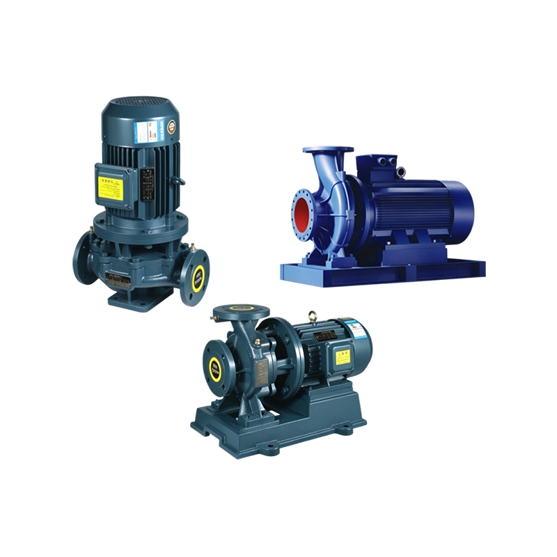
Pairing a three-phase asynchronous motor with a variable-frequency drive allows speed to be adjusted smoothly across a wide range, which is common on fans, pumps and conveyors where flow or throughput needs to track a changing process demand rather than run at a single fixed speed.
For coal mining, petrochemical and other hazardous-area installations, explosion-proof enclosures contain any internal arcing or sparking so it cannot ignite surrounding flammable gas or dust, allowing a three phase electric motor to operate safely in zones where a standard open enclosure would not be appropriate.
Working through the following order generally narrows the field quickly, whether the target is a small aluminum-housed unit or a large cast-iron industrial three phase motor.
A simple starting formula for three-phase power is P (kW) = (root three x V x I x power factor x efficiency) / 1000, using line voltage V and line current I. For a known mechanical load, shaft power in kW can also be estimated from torque and speed as P = (Torque in Nm x Speed in rpm) / 9550, then rounded up to the next standard frame rating with a reasonable starting margin.
Horsepower and kilowatts describe the same output using different units, related by roughly 1 hp = 0.746 kW. Rather than picking a horsepower figure in isolation, it helps to work backward from the driven equipment's manufacturer data or measured running current, since an undersized motor will run hot under normal load while an oversized one carries unnecessary weight and a lower operating power factor at partial load.
A three phase induction motor is mechanically simple, but a short routine still goes a long way toward keeping running hours predictable.
Following a simple schedule like this tends to extend the practical service life of a three phase AC motor considerably more than reacting only after a fault appears.
Q1. What is a three phase asynchronous motorIt is an AC motor that uses a rotating magnetic field in the stator to induce current in the rotor, creating torque without any direct electrical connection to the rotor itself. |
Q2. How does a three phase induction motor workThree-phase current in the stator windings produces a rotating field; this field induces current in the rotor bars, and the interaction between the two fields turns the shaft. |
Q3. What is the difference between an asynchronous motor and an induction motorThey describe the same machine. Asynchronous refers to the rotor speed lagging the field speed, while induction refers to how current reaches the rotor, through induction rather than a direct connection. |
Q4. What are the advantages of a three phase induction motorSimple squirrel-cage construction, self-starting without a capacitor, steady running speed under varying load, and a wide available power range from fractional kilowatts up to hundreds of kilowatts. |
Q5. What are three phase motors used forFans, pumps, compressors, conveyors, machine tools, and general industrial equipment across manufacturing, energy, mining, textile and port handling settings. |
Q6. How do I choose a three phase induction motorStart from the driven load type and required speed, size shaft power with a starting margin, then match pole count, housing and protection rating to the installation environment. |
Q7. How do I calculate the motor size I needEstimate shaft power from load torque and speed using P equals torque times speed divided by 9550, then round up to the nearest standard frame rating with a reasonable margin. |
Q8. How do I choose motor horsepowerWork from the driven equipment's actual power requirement rather than guessing, converting between horsepower and kilowatts using roughly 1 hp equals 0.746 kW. |
Q9. How many poles should my motor havePick the pole count whose synchronous speed sits closest to the desired output speed, since this generally reduces the size of any additional gearbox or pulley reduction needed. |
Q10. What maintenance does a three phase motor needRoutine attention to cooling airflow, bearing lubrication, vibration levels, and terminal box connections covers most of what keeps a unit running reliably over time. |



 English
 Español
 عربى
عربى